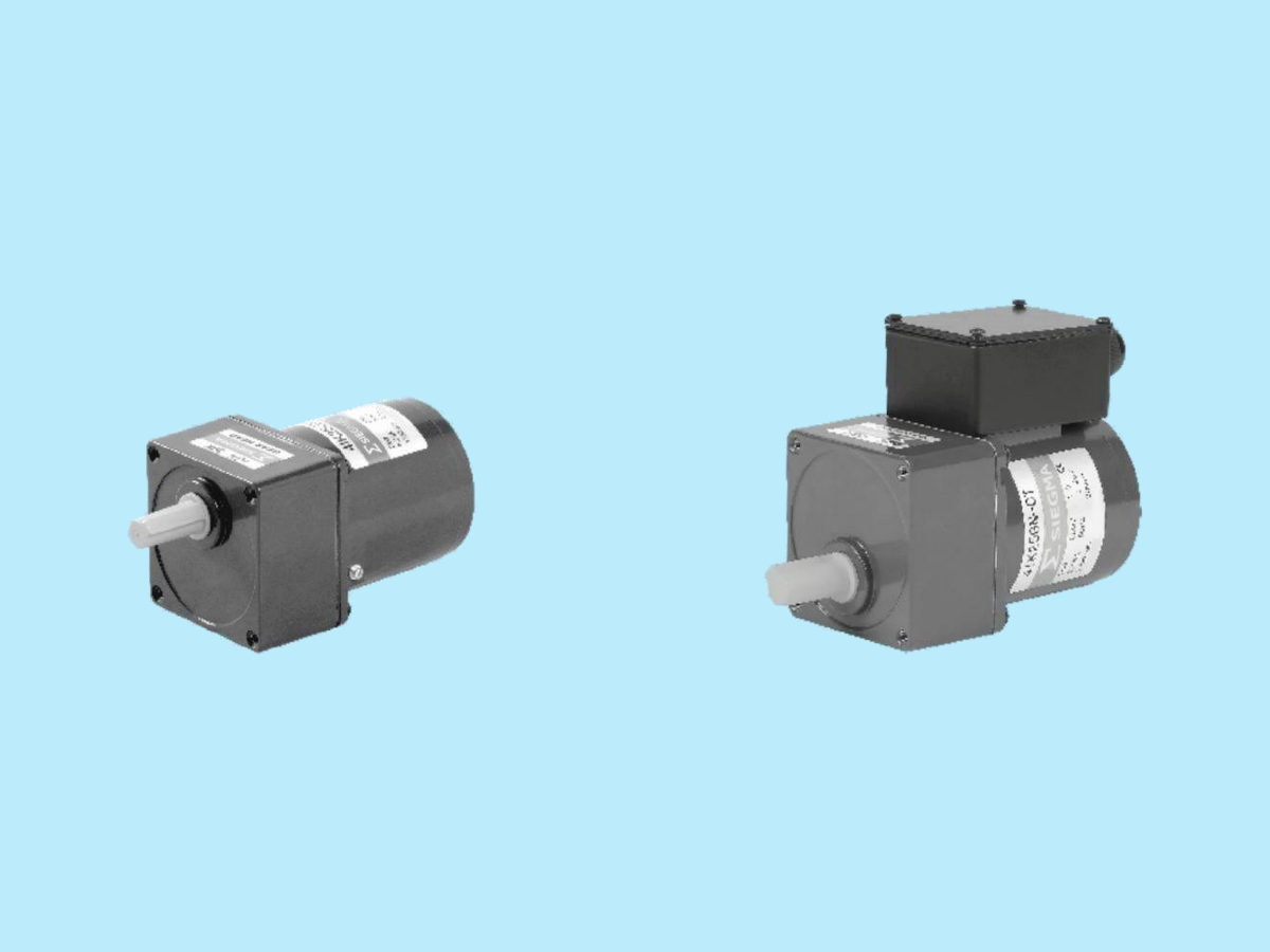
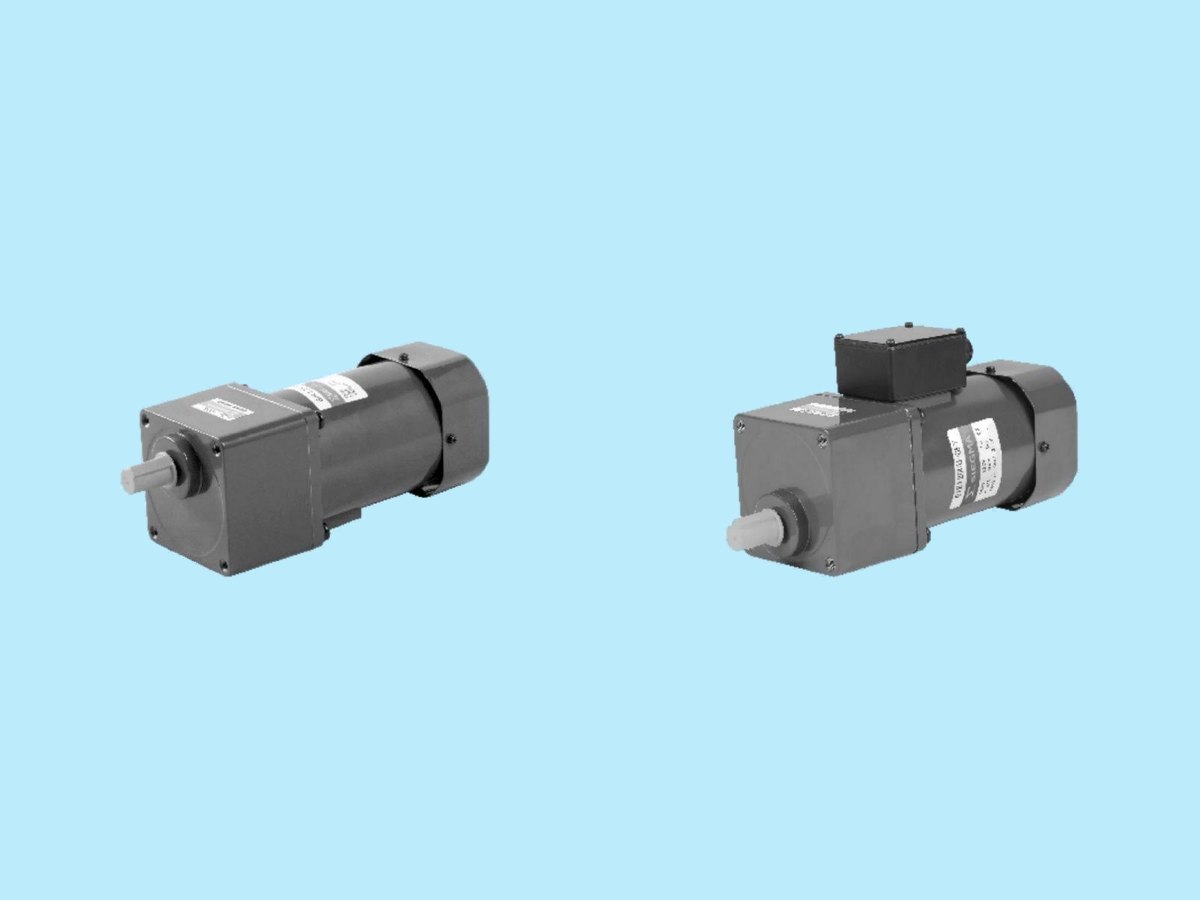
AC Induction Gearmotors
SIEGMA's primary line of micro AC induction gear motors. Square-frame single- or three-phase induction motors paired with long-life, low-noise parallel-shaft GN gearheads. Built for continuous-duty industrial use across a 3 W to 200 W power band.
Download AC inline catalog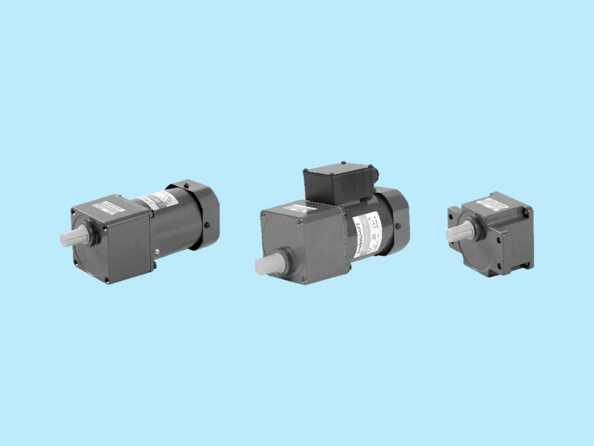
Continuous-duty by design.
Single & three-phase
Capacitor-run single-phase units, or three-phase units for higher starting torque and efficiency.
Built-in thermal protector
Automatic-return thermal protector trips at 120 °C (Class B) or 145 °C (Class F) ± 5 °C.
UL/CSA Class A insulation
Class A (105 °C) UL/CSA, Class B (130 °C) per EN. Insulation resistance ≥ 100 MΩ, 1.5 kV / 1 min withstand.
IP54 terminal box
25–180 W terminal-box variants meet IP54; lead-wire variants are IP20.
Pinion & round-shaft
GN pinion-shaft to mate with the GN gearhead, or A-coded round-shaft (with optional A1 keyway).
Rotatable junction box
Gearhead orientation supports lead/junction-box rotation at 0°, 90°, 180°, or 270°.
IK series motor data.
Power, frame, and rated speed
Frame size scales with output power. Rated speeds shown at gearhead input.
| Output | Frame size | Rated speed (50 Hz / 60 Hz) |
|---|---|---|
| 3 W | 42 mm sq. | 2500 / 3000 r/min (2-pole high-speed) |
| 6 W | 60 mm sq. | 1200 / 1450 r/min |
| 15 W | 70 mm sq. | 1200 / 1450 r/min |
| 25 W | 80 mm sq. | 1250 / 1550 r/min |
| 40 W | 90 mm sq. | 1250 / 1550 r/min |
| 60 W | 90 mm sq. | 1250 / 1550 r/min |
| 90 W | 90 mm sq. | 1250 / 1550 r/min |
| 120 W | 90 mm or 104 mm sq. | 1250 / 1550 r/min (90 mm); 1300 / 1600 r/min (104 mm) |
| 140 W | 104 mm sq. | 1250 / 1350 / 1550 / 1600 r/min |
| 200 W | 104 mm sq. | 1250 / 1550 r/min |
Torque ratings
Starting torque and rated torque, in mN·m. Ranges reflect available phase / voltage variants per frame.
| Output | Starting torque | Rated torque |
|---|---|---|
| 3 W | 5 | 10–11 |
| 6 W | 40–85 | 40–50 |
| 15 W | 65–220 | 105–125 |
| 25 W | 120–350 | 165–250 |
| 40 W | 200–800 | 250–660 |
| 60 W | 300–1000 | 380–800 |
| 90 W | 450–1350 | 570–1100 |
| 120 W (90 mm) | 600–1850 | 750–1600 |
| 120 W (104 mm) | 600–2200 | 750–2000 |
| 140 W | 700–2700 | 850–2200 |
| 200 W | 850–3400 | 1230–2700 |
General specs
| Voltages | Single-phase 100 / 110 / 120 / 220 / 230 V (50/60 Hz). Three-phase 200–230 V or 380–415 V (50/60 Hz). |
|---|---|
| Synchronous speed (4-pole) | 1500 r/min @ 50 Hz; 1800 r/min @ 60 Hz. Actual speed runs 2–20% below sync depending on load. |
| Insulation | UL/CSA Class A (105 °C); EN Class B (130 °C) |
| Insulation resistance | ≥ 100 MΩ |
| Insulation voltage | 1.5 kV (2 kV for 3-phase 400 V) for 1 minute |
| Winding temperature rise | ≤ 80 °C with gearhead or equivalent heat-sink plate |
| Protection class | IP20 (lead wire); IP54 (terminal box, 25–180 W) |
| Ambient temperature | −10 to +50 °C (1ph 100 V / 3ph 200 V); −10 to +40 °C (others) |
| Ambient humidity | ≤ 85% non-condensing |
GN gearhead — ratios & output torque
| Available ratios | 3, 3.6, 5, 6, 7.5, 9, 10, 12.5, 15, 18, 20, 25, 30, 36, 40, 50, 60, 75, 90, 100, 120, 150, 180, 200 |
|---|---|
| Decimal gearhead | 10:1 add-on (e.g. 2GN10XK) for further reduction |
| Allowable output torque (gearhead ceiling) | 3 W: ~0.44 N·m · 6 W: 3 N·m · 15 W: 5 N·m · 25 W: 8 N·m · 40–60 W: 10 N·m · 90 W: 20 N·m · 120 W+: 20–40 N·m |
3IK15GN parallel-shaft gearmotor
Dimensional drawing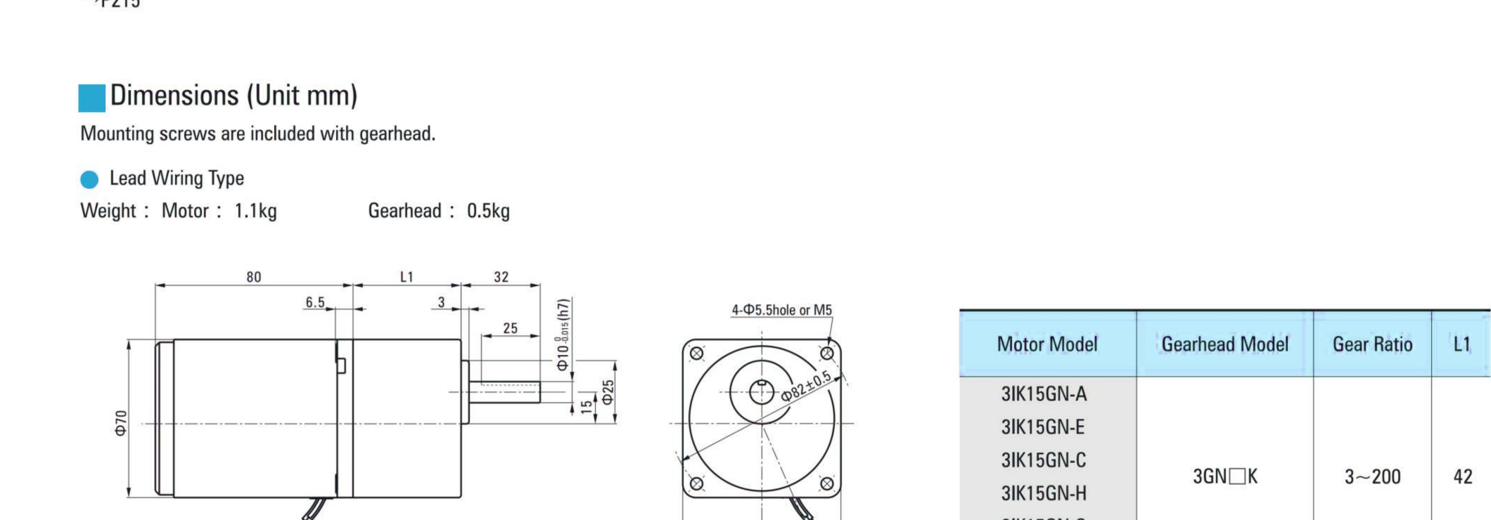
Model number breakdown.
IK motor numbers follow an eight-position scheme. Example: 5IK40R GN-CT
| Position | Field | Options |
|---|---|---|
| 1 | Frame size | 0 = 42 mm · 2 = 60 mm · 3 = 70 mm · 4 = 80 mm · 5 = 90 mm · 6 = 104 mm |
| 2 | Motor type | I = Induction · R = Reversible · T = Torque |
| 3 | Series | K (K series) |
| 4 | Output power | Watts (e.g. 40 = 40 W) |
| 5 | Speed-adjustable | R suffix indicates speed-adjustable variant |
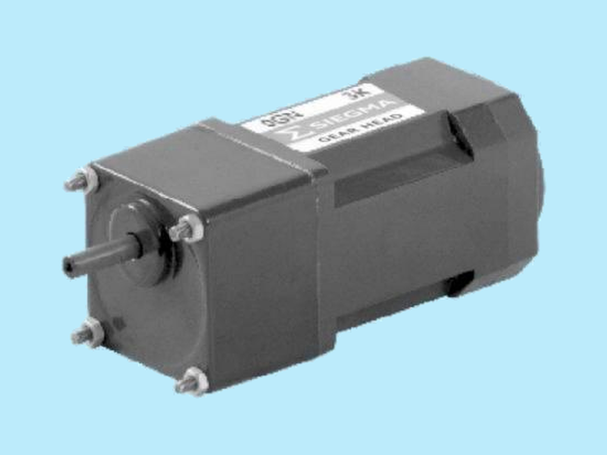
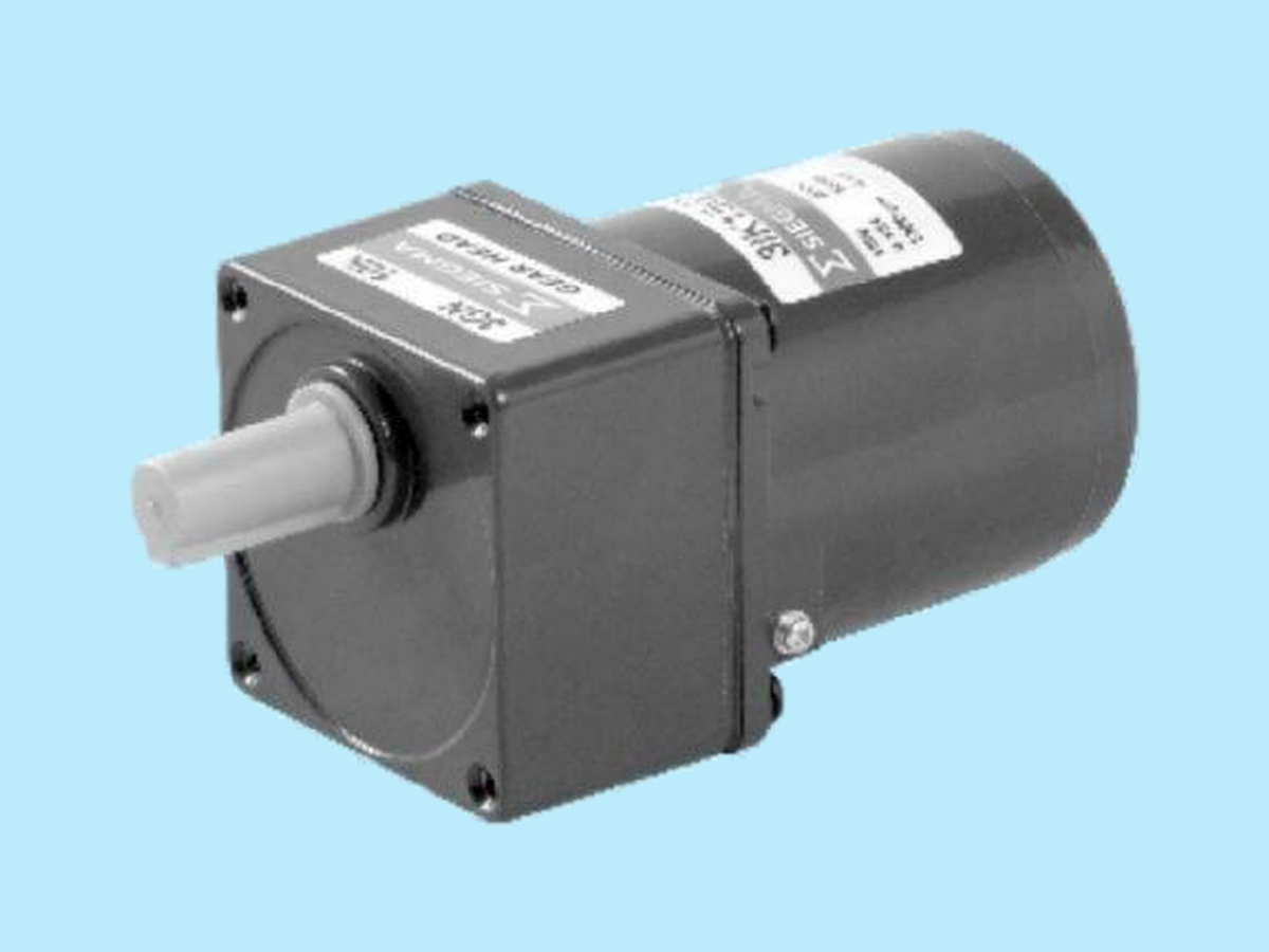
| 6 | Shaft type | GN = parallel-shaft pinion · GU = right-angle pinion · A = round shaft · A1 = round shaft with keyway |
| 7 | Voltage / pole code | A = 1ph 110 V/60 Hz 4P · B = 1ph 110 V/50 Hz 2P · C = 1ph 220-230 V/50 Hz 4P · D = 1ph 220 V/50 Hz 2P · E = 1ph 110-120 V/60 Hz 4P · H = 1ph 220-230 V/60 Hz 4P · S = 3ph 200-230 V 4P · T = 3ph 200-230 V 2P · S3 = 3ph 380-415 V 4P · T3 = 3ph 380-415 V 2P |
| 8 | Variant | T = terminal box · F = with fan · FF = forced fan · M = power-off-activated electromagnetic brake |
Gearhead format: 5GN50K — frame size + GN/GU + ratio + bearing flag (K = make-KB for GU square-case). Decimal-gearhead variants carry an "X" prefix (e.g. GN10XK).
Reversible, brake, and 2-pole variants.
The IK induction lineup is the primary product on this catalog page. The same motor platform also supports several factory variants documented in the source catalog.
RK reversible motors
Built-in friction brake (spring-loaded disk) for instant-reversal duty. Keeps ~10% of rated torque when stopped and shortens over-run to 4–6 cycles depending on frame.
Electromagnetic brake
Power-off-activated brake variants offer 0.05–2.0 N·m brake torque. Stops and reverses the motor up to 6 times per minute (each cycle ≥ 3 s).
2-pole high-speed
Bare 2-pole induction motors covering 6 W to 150 W in 60 / 70 / 80 / 90 mm frames. Rated speeds in the 2600–3200 r/min range.
Speed-control units
Bundled motor + controller for potentiometer-adjustable operation between 90–1400 r/min @ 50 Hz or 90–1700 r/min @ 60 Hz.
Where IK series fits.
General-purpose industrial drives for conveyors, indexers, packaging machinery, and food processing equipment (an oil-cup option is available to prevent oil leakage in food-machinery use). Three-phase units are well suited to higher-load applications needing strong starting torque.
- Conveyor drives
- Indexing tables
- Packaging machinery
- Food processing
- Textile machinery
- Automated assembly
- Light agitators
IK series imagery.
AC Inline Gearmotor — Full catalog
Complete IK / GN line coverage including 2-pole high-speed motors, reversible-motor characteristics, electromagnetic-brake parameters, and full per-frame spec sheets.